Wiring an S13 SR20DET up for an S14 (95-98)
If you've come here then you have decided to undertake the task of wiring up an s13sr20det motor for use in a 1995-1998 240sx. This isn't the end all guide or going to go over problem free for you if it's your first time wiring up an engine. But it will get you set on the right path. - Wayne
Un-loomed
The other two plugs you need from the KA harness. You can remove the F2 plug from the equation and have the ECU in an ALWAYS on state to ensure your ecu will always get power no matter what, but Jeff Jordan removed this from the harness for me.


I decided to move the wiper amp into the cabin instead of having it in the engine bay, honestly I think in the end it made no difference since you cant even tell it's there already....
At this point the only work I really needed to do was wire up the f3 plug and the wipers. That's really all you're doing when attempting this. It's a lot simpler than people try to make it seem.
You're pretty much at the point of no return if you have gotten this far. You can either continue to read the instructions, or you can pay a professional who knows what they're doing to finish this part for you.
This stuff below is super useful, I highly suggest printing it out and keeping it by your side as quick reference.
If you want to make the install a little cleaner you can move your igniter and wiper amp inside of the cabin. Some double sided tape on the igniter so it sits on the ecu bracket. (SMART)

Again super stupid simple, cut, solder, heat shrink, move along. You can use the skinny 02 from the redtop if you're going to keep the oem downpipe, if you go aftermarket downpipe you'll need a fat 02 sensor the KA24DE fat 02 sensor WILL WORK. So don't be so quick to sell them off or throw them away.
O2 Sensor- F3 S14 KA to F10 S13 SR Harness (See EC-164)
The original author made this sound so intimidating, it's quite simple really. You find this guy and put it off to the side, all you do is match the colors to the same wires on the F3 plug on the KA harness, super simple. I never did get the water temperature to work for some odd reason. But I run an aftermarket temp gauge anyway and I'd recommend you do the same.
Personal feedback There is a 4 prong harness plug here on the IACV itself so this is really vague! the IAVC also has the AAC wiring on it as well.
F7-S14 KA and F9-S14 KA are both located in the engine bay, against the firewall, on the passenger side. This is something else the original author made WAY more complicated than it needed to be. Refer to the wiper plug pictures at the beginning of the write up if you need to VISUALIZE them.
And that's pretty much it, once you get this nailed down then it's a matter of testing everything and then going back step by step to ensure everything is in working order before you go taping it up or looming it, etc, etc. - Wayne

Tips before you get started on buying stuff.
- make sure you only use adhesive heat shrink. Just so happens a strand of h/s I bought wasn't adhesive and the solder ended up corroding causing shorts/issues. I had to cut open the whole harness and replace all of the heat shrink to be sure.
- Extra runs of wiring aren't really necessary to do this, you can use wires from your ka24de harness that are already color matched and the same gauge.
- The s13sr20det harness can have about 3-4 inches removed from it behind the firewall (in car) but don't make any cuts until you know everything works, then shorten as desired.
- If you break a plug/connector (use your brain and borrow one from the ka24de harness)
-------------------------------------------------------
Introduction from the original how-to
Installing a S13 SR20DET (red or blacktop) into a 1995 240sx is a very simple task that is not much more difficult than putting the same motor into a S13 chassis.There are a few details that make this swap a bit different from swapping into the S13 chassis. The Upper Engine Harness on the S14 (KA and SR) has the plugs for your:
- Windshield wiper motor
- Windshield wiper amplifier
- ABS sensor for right front wheel
- ASCD (cruise control).
You will need to rewire all of the accessories that you have on your car to make them work with your engine and S13 SR20DET harness.
Anyway lets jump into this... I will be wiring the charging system/lower harness separately from the engine harness and transmission harness... You can read how I made my lower harness by clicking HERE.
 |
Before I started, the SR harness is on the left, and the KA harness is on the right.
|
Here is the wiper plug (F7) from the KA harness. (The plug looks different for a 97-98)
 |
This is the Wiper Plug you will need from your 95-96 KA24DE harness to retain wipers.
The plug at the end is different for a 97-98 and the pin out is different but they both get wired up the same way.
|
Un-loomed
 |
95-96 wiper motor plug
|
 |
| 97-98 wiper motor plug (do not re-pin this) just wire it up the same way you would the 95-96 |
The other two plugs you need from the KA harness. You can remove the F2 plug from the equation and have the ECU in an ALWAYS on state to ensure your ecu will always get power no matter what, but Jeff Jordan removed this from the harness for me.
 |
F2(blue plug) and F3(black/white plug)
|
If you plan on installing/hooking up your windshield wipers you will also need the F9 plug (wiper amp)

In total you will need to clip all of these from the KA24DE harness for your s14. So don't think about trying to make a buck off of it by selling it with that motor you have laying around now.

If you are unfamiliar with S14's, you will also find the following differences from the S13
- Power plugs on the S14 are under the dash (near the ECU)
- ECU relay is also found under the dash (near the ECU) instead of in the engine compartment as found on the S13.
Now we want to take the redtop plugs (F10-Brown/Green and F8-Gray) and pull them through the grommet to wire up our F3 plug on the inside the cabin that controls a majority of important functions for your SR20DET Redtop


 |
| Pull the two plugs pictured through this guy. I eventually cut a slit on the side of the grommet to make this easier. |
You will need to do one of those plugs at a time while doing the F3 power plug so you don't get the wires mixed up as they both have brown wires.(Or you can mark all of the wires and just cut the plug ends off.)
The original write up recommends making a sub harness of some sort, I never really got that whole part of the write up. My point is it suggests for you to locate the plug for the s13 instrument cluster for this or you can hardwire it. All of the colors are the same (or should be) for the instrument cluster wiring which you hardwire into your F3 plug. I was never able to get the temp readout to work on the oem cluster. All of the wiring checks out and a signal is being sent. But you should run an aftermarket temp sensor/gauge anyway.
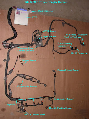
I laid the engine harness out in the engine bay to go through a process of elimination determining where everything should go. I got a cheat sheet from Jeff Jordan of Jordan Innovations that dumbed down all of the engine harness lingo from the fsm (Factory Service Manual).

This is the cheat sheet courtesy of my buddy Jeff. Please don't ask for a better picture it doesn't exist.
 |
| I checked off what I found/matched up. The rest was a mystery that needed solving. |
 |
| Here I am separating the wiring for the window wiper and grouping it together for later. |
At this point the only work I really needed to do was wire up the f3 plug and the wipers. That's really all you're doing when attempting this. It's a lot simpler than people try to make it seem.
You're pretty much at the point of no return if you have gotten this far. You can either continue to read the instructions, or you can pay a professional who knows what they're doing to finish this part for you.
I would highly recommend wiring specialties for an off the shelf plug and play harness if you have the money to go that route. I am more of a do it yourself kind of guy, plus I wanted to do a wire tuck and loom. I did have a lot of setbacks and had to open my harness up about 4 times. So if that doesn't scare you off from continuing I'll give you one last chance to re-consider
Still here, alright then.
--------------------------------------------------------------
This stuff below is super useful, I highly suggest printing it out and keeping it by your side as quick reference.
Wiring Details:
OR- Orange
LG- Light Green
B- Black
PU- Purple
P- Pink
BR- Brown
R- Read
W- White
G-Green
L- Blue
Y- Yellow
GY- Gray
SB- Sky Blue
LG/R-Light Green w/ Red Stripe
LG/B- Light Green w/ Black Stripe
L/Y- Blue w/ Yellow Stripe
B/P- Black w/ Pink Stripe
B/W- Black w/ White Stripe
R/B- Red w/ Black Stripe
B/Y- Black w/ Yellow Stripe
B/R- Black w/ Red Stripe
L/R- Blue w/ Red Stripe
Y/G- Yellow w/ Green Stripe
Y/R- Yellow w/ Red Stripe
L/B- Blue w/ Black Stripe
 |
| KA24DE S14 "F3" Pinout |
 |
| 1991-1996 S13 SR20DET REDTOP/BLACKTOP ECU Pinout J2/J3/E4/E5 |
 |
| Pin out for F1/F9/F10 Connector from S13 SR20DET Harness you will need to wire up to the S14 F3 plug |
 |
| Literal wiring write up by my buddy Phi Hoang (nrg) |
 |
| You can remove this from the harness (no I don't know what it is but it's not relevant.) |
------------------------------------------------------------------
Fuel Pump Relay
Connect one wire from F10-S13 SR to the power plug F3- S14 KA
Fuel Pump Relay- F3 S14 KA to F10 S13 SR Harness (See EC-201 S14 FSM)
F3-S14
KA
|
F10-S13
SR
|
Identification
|
27-B/P
|
2-B/P
|
(Fuel
Pump Relay)
|
ECU Relay
This is pretty straight forward. You need to power the ecu relay from F3-S14 KA plug and then run wires to the power plugs on the S13 SR harness. (you can also just eliminate the relay and always have power w/ignition on running to the ecu. I will not be covering how to do that.)
F3-S14
KA
|
F2-
S14 KA
|
Identification
|
17-R
|
2-R
|
(Power
to Relay)
|
17-R
|
5-R
|
(Power
to Relay)
|
F8-
S13 SR
|
F2-S14
KA
|
Identification
|
2-B/W
|
3-B/W
|
(Ecu
Power)
|
F10-S13
SR
|
F2-S14
KA
|
Identification
|
4-R/B
|
1-R/B
|
(Ecu
Relay)
|
(I have corrected the pin out numbers for F3 since they were incorrect on the original write up)
ECU Backup
You need to run one wire from the S13 SR power plug to the F3-S14 KA power plug. Make this about 4-5' long depending on where you put your S13 power plugs in relation to F3-S14 KA.
ECU Backup- F3 S14 KA to F8 S13 SR Harness (See EC-85 S14 FSM)
ECU Backup
You need to run one wire from the S13 SR power plug to the F3-S14 KA power plug. Make this about 4-5' long depending on where you put your S13 power plugs in relation to F3-S14 KA.
ECU Backup- F3 S14 KA to F8 S13 SR Harness (See EC-85 S14 FSM)
F8-S13
SR
|
F3-S14
KA
|
Identification
|
1-R
|
9-R
|
(ECU
Backup)
|
Ignition Power and Coilpack Power
Now the fun part... the ignition power, and coil power, to power (F3-1), this one took a while for the solder to finally penetrate ALL of the wire...
 |
| See the following below |
--------------------------------------------
Make this about 4-5' long depending on where you put your S13 power plugs in relation to F3-S14 KA.
Make this about 4-5' long depending on where you put your S13 power plugs in relation to F3-S14 KA.
Ignition Power & Coilpack Power- F3 S14 KA to F8 S13 SR Harness (See EC-106 S14 FSM)
This should be pretty straight forward, you need to make those two wires (B/R) & (L/R) go into pin number 1 (B/R) on the F3 plug. I always get questions/emails about this since some people seem to read over this step. *NOTE : L= Blue, B= Black, R= Red
If you screw this up, the coil pack igniter will not receive power, thus no power to fire your spark plugs. This is basically the ON switch for your motor. So don't screw up, make sure that solder joint is on point and fully penetrated to make sure full power is flowing through these wires otherwise you may end up getting some break up when you start to buy power adders.
If you screw this up, the coil pack igniter will not receive power, thus no power to fire your spark plugs. This is basically the ON switch for your motor. So don't screw up, make sure that solder joint is on point and fully penetrated to make sure full power is flowing through these wires otherwise you may end up getting some break up when you start to buy power adders.

 |
| You will find a lot of random wires like this taped off to the side on engine swap harnesses. This is consult plug wiring I believe. I removed them. |
O2 Sensor
Again super stupid simple, cut, solder, heat shrink, move along. You can use the skinny 02 from the redtop if you're going to keep the oem downpipe, if you go aftermarket downpipe you'll need a fat 02 sensor the KA24DE fat 02 sensor WILL WORK. So don't be so quick to sell them off or throw them away.
O2 Sensor- F3 S14 KA to F10 S13 SR Harness (See EC-164)
F10-S13
SR
|
F3-S14
KA
|
Identification
|
7-BR
|
10-BR
|
(O2
Sensor Power)
|
Instrument Cluster
The original author made this sound so intimidating, it's quite simple really. You find this guy and put it off to the side, all you do is match the colors to the same wires on the F3 plug on the KA harness, super simple. I never did get the water temperature to work for some odd reason. But I run an aftermarket temp gauge anyway and I'd recommend you do the same.
 |
| Do not chop this off until you're ready to wire the cluster up. |
S13
SR Instrument Plug
|
F3-S14
KA
|
Identification
|
Y/G
|
16-Y/G
|
(VSS
See EC-103)
|
Y/R
|
18-Y/R
|
(TACH
See EL-76)
|
B
|
Ground
to Chassis
|
(Ground
See EC-85)
|
OR
|
34-OR
|
(Ignition
Start See EC-198)
|
L/B
|
20-Y
|
(Water
Temperature See EL-76)
|
IACV
IACV- F3 S14 KA to F8 S13 SR Harness (See EC-216, EC-112 S14 FSM)
F8-S13
SR
|
F3-S14
KA
|
Identification
|
6-B/Y
|
26-B/Y
|
(IACV
Power)
|
Personal feedback There is a 4 prong harness plug here on the IACV itself so this is really vague! the IAVC also has the AAC wiring on it as well.
 |
| If you can afford to, buy a new one. Most of these are all clogged and dirty or just dead and you'll go nuts trying to dial in a 900rpm idle if this part isn't functioning correctly. Plus the plastic adjustment screw ALWAYS strips. Adjust with pliers. |
Just leave all of the wires in tact on the IACV itself and don't remove the aac wiring. It may be the difference between your car finding idle, or sitting at 2grand like mine does. Biggest annoyance ever.
Wiper Motor and Wiper Amplifier
F7-S14 KA and F9-S14 KA are both located in the engine bay, against the firewall, on the passenger side. This is something else the original author made WAY more complicated than it needed to be. Refer to the wiper plug pictures at the beginning of the write up if you need to VISUALIZE them.
Wiper Amp F9 S14 KA to F7 S14 KA and F3 S14 KA (See EL-102 S14 FSM)
|
||
F7-S14
KA
|
F9-S14
KA
|
|
1-OR
|
8-OR
|
|
2-LG
|
6-LG
5-LG(F3-S14 KA) |
|
6-B
|
7-B
Ground
|
|
F7-S14
KA
|
F3-S14
KA
|
|
2-LG
|
6-LG
(Wiper Amplifier)
5-LG |
|
4-LG/R
|
7-LG/R
|
|
5-LG/B
|
6-LG/B
|
|
Wiper Amp F9 S14 KA to F7 S14 KA and F3 S14 KA (See EL-102 S14 FSM)
|
||
F9-S14
KA
|
F7-S14
KA
|
Identification
|
6-LG
|
5-LG
(F3)
2-LG |
(IGN)
|
7-B
|
6-B
Ground to Engine |
(GND)
|
8-OR
|
1-OR
|
|
F9-S14
KA
|
F3-S14
KA
|
Identification
|
1-L/Y
|
19-L/Y
|
(INT/SW)
|
2-PU
|
42-PU
|
(INT/VR)
(SE ONLY)
|
4-BR
|
8-BR
|
(OFF
& INT SW)
|
5-P
|
4-P
|
(WASH
SW)
|
6-LG
|
5-LG
2-LG (Wiper Motor) |
(IGN)
|
And that's pretty much it, once you get this nailed down then it's a matter of testing everything and then going back step by step to ensure everything is in working order before you go taping it up or looming it, etc, etc. - Wayne
Resources:
S13 SR20DET Installation Into 1995 240sx
I am keeping a link to the original web archive where I initially found my instructions. Forbid they eventually die off of the web I am going to copy a lot of it and paste it on my blog for preservation sake. 6/20/11 - Wayne