I've narrowed it down but have not found the problem.
Man oh man am I going to be skull crushing today to figure this one out.
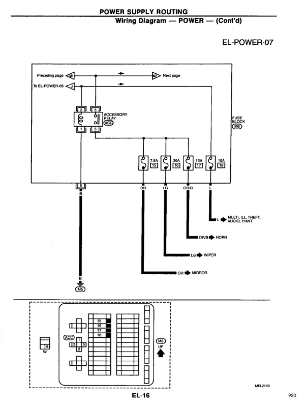
In a nutshell the kick panel fuse box on the driver side has 4 relays in it. The first relay seems to be where my chassis grounding issue is. So it's a matter of tracing the pins that go to this relay. And finding out how it's grounding to the chassis.
If I unplug the cable that goes to this relay slot the continuity between the positive power and negative post go away. If I remove the relay while the plug is still there. Continuity still exists, meaning no power since it's a constant ground on both + and -.
EL14 through EL-17 is what will be needed for todays homework from the factory service manual. Anyone want to chime in where they think the culprit lays?

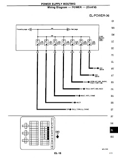


To give you a hint on what you're looking at. The plug in question has 2 large white wires with blue stripes on this diagram white is W and blue is L. This would be referenced by a (first color / second color) designation, for example. White/Blue would be W/B.
The reason blue is listed as L is because B stands for black. So this can get confusing, there is a reference on what the wire colors are and how to read them at the beginning of the factory service manual.
So yeah, time to break out the highlighter. I'll report back later with my findings.
In a nutshell the kick panel fuse box on the driver side has 4 relays in it. The first relay seems to be where my chassis grounding issue is. So it's a matter of tracing the pins that go to this relay. And finding out how it's grounding to the chassis.
If I unplug the cable that goes to this relay slot the continuity between the positive power and negative post go away. If I remove the relay while the plug is still there. Continuity still exists, meaning no power since it's a constant ground on both + and -.
EL14 through EL-17 is what will be needed for todays homework from the factory service manual. Anyone want to chime in where they think the culprit lays?


To give you a hint on what you're looking at. The plug in question has 2 large white wires with blue stripes on this diagram white is W and blue is L. This would be referenced by a (first color / second color) designation, for example. White/Blue would be W/B.
The reason blue is listed as L is because B stands for black. So this can get confusing, there is a reference on what the wire colors are and how to read them at the beginning of the factory service manual.
So yeah, time to break out the highlighter. I'll report back later with my findings.