So you wanna install one of these. I'll try to be the voice of reason in 2022 and tell you it's probably not even worth it. 10-15 years ago, heck yeah go for it.
But if you're insistent like myself, I'll give you all of the tools needed to get the job done.
It's been a while since I've installed this. 12 years in fact. I've contemplated making youtube videos but to be honest I am ungodly lazy. This blog post at this point is more of a diary for me as well as a how-to because if I ever have to troubleshoot this crap again I know that I've unnecessarily over-documented this install for the final time.
I will say that, I originally followed the write up here: chuonthis s14 dcc write-up I don't want to plagiarize and flat out copy the write up, but I'm going to stage the information very similarly.
I have it available in PDF format and have uploaded it here in case their website ever goes down. I recommend saving that.
Other Useful Documents. I took the liberty of OCR Scanning the manuals and uploading them if you need them.
I want to make sure you don't make the same mistakes I did while installing this.
Note: If you want to do live testing of your wiring section by section, you'll need to wire up Pin number 11, 12, and 20 following the guide below.
Realistic Expectations
While this photo looks bad, expect the buttons on these units to be broken. And if they're not, expect the price of the goods to be higher, either/or there is a solution for the lack of quality available. This is what I did to repair mine
Recommended Tools
A terminal removal tool. I just use a really long jewel flathead screwdriver.
Wire Stripper of some sort
Wire Crimper
Electric tape
What you should purchase
Ideally you want to buy something like the photo below. Almost every OEM part you can buy for an s-chassis is discontinued. Some of the alternative Maxima and Altima sensors suggested have also become harder to come by due to those models having their parts discontinued.
If you buy one of these units and you're unable to source the sub-harness with the pigtails. An alternative is to buy new connectors and wire terminals. I found this website https://connectorexperts.com and it looks like they have the plugs on their site.
TERM432 for the terminals that go inside of the plug you'll need roughly 8 of them they're sold only in packs of 10 (most wires you can just re-pin, for any additional wires this should sort you out)
Note: If you're not running the airbag system the airbag control unit is under the rear passenger seats. Those pin's will fit. That's where I sourced two pinned flying leads for the air-mix motor.
For replacement led lights for the digital climate control unit I bought NEO5-NWHP: 5mm NEO5-xHP Natural White from SuperBrightLeds you will need to trim the little locking hooks on them to actually get them to turn and lock into place. I was also unable to use any screwdriver I owned to lock them in place. Just an fyi, there is a positive and negative terminal so if your lights don't come on just take the bulbs out and rotate them 180 degrees clockwise and re-seat them.
Wiring
I can't really remember where in the fsm the wiring descriptions are. Most folks who have scanned them never upload those pages, or the super multiple junction pinouts. Either way I will just say B = Black always and L = Blue
Also I will reference plugs using both their JDM/UKDM and USDM counterparts so if you're using the plug location guides posted just a bit down from here. It will make a little more sense where you're looking.
I've revamped the pinout guide including a color guide. I recommend checking things pin to pin anyway you can download thePDF Here of the charts below
I also want to say since we're focused on doing a USDM to JDM Climate Control swap here. I kept the wiring chart centric to the jdm sub harness plugs. So while the abbreviations below still work I didn't want to confuse anyone by using the plug names for the USDM plugs since they're named different in the JDM/UKDM FSM. I couldn't imagine how frustrating that would be 🙄
FS = Fan Switch (M35 referred to as M33 in the JDM/UKDM FSM for LHD)
BM = Blower Motor (M54 referred to as M53 in the JDM/UKDM FSM for LHD)
ICS = In Cabin Sensor / In-Vehicle Sensor (M26)
SS = Sunload Sensor (M46)
FCA = Fan Control Amp (M50)
AMDM = Air Mix Door Motor (M33 referred to as M27 in the JDM/UKDM FSM for LHD )
circuit diagrams side by side
You need to remove your dash
Others will say it's not necessary, one way or another it's gonna come off. I'm just keeping it real. This is also the best way to troubleshoot the system before you consider it completed. Good opportunity to clean everything under there too, lots of dust bunnies in here. *barf* The video below is probably the best how-to I found.
Component locations
Here are the sensor or component locations next to each other. Pay attention to the component name/numbers as they will be referenced throughout this write up. I will try to post reference pictures again in each section.
Sensors
Sunload Sensor
I'm just going to start out by linking this. If you can get this thing off and put it back after drilling a hole in it. and then pressing your sensor in. You deserve an award, the sunload sensor has a little retaining clip on it to help it snap into place. So be mindful how big of a hole you put in your defrost vent. You'll see below on the dashboard there is already a pre-cut hole you can run this through. (Altima Part Number 27721-0E000). The one I have pictured is the S-Chassis sunload sensor.
The sunload sensor wiring for this install is as follows.
(M31 JDM/UKDM 16pin) pin #26 OR to (M46 JDM/UKDM) pin #1
Note: Sensor Grounds for M46, M26, and E46 will meet at M31(16pin) pin #29
Ambient Temp Sensor
Just pointing this out the USDM S14 has an ambient temperature sensor in the engine bay already. The one installed is E36 pictured below. It cannot be used or utilized. It's ground to the engine and it has a L/W wire that goes through the driver side firewall body harness grommet, to the super multiple junction M9/E101 that runs to the M63/F3 plug at pin 29. It contributes to the control of your car's idle based on ambient engine bay temps. You need both wires to make it back to the DCC unit.
E36 right by the hood latch is the USDM Ambient Temp Sensor.
The Ambient Temp sensor wiring for this install goes as follows.
Note: Sensor Grounds for M46, M26, and E46 will meet at M31(16pin) pin #29
This pigtail harness from wiring specialties should fit this sensor
I have mine mounted just outside of the engine bay. I'm just referencing fsm colors, the wires can be any color you want as long as you know what pin is which color.
Note: Sensor Grounds for M46, M26, and E46 will meet at M31(16pin) pin #29
Altima Part 27720-31U00 pretty sure I bought the last one in america
For the in-cabin air temperature sensor I originally just taped it down where the cruise control switch would go in our cars since I don't have cruise control. I purchased a jdm cluster surround with the sensor after buying a brand new oem altima sensor as well. Just to have options. I'm going to look into possibly retrofitting the sensor here so it looks oem.
I will try to provide some more information as I progress on this one about getting a hose that fits the sensor as well. I purchased the suggested aspirator (Altima, Pathfinder part number : 27726-0P000)
Will probably make an entirely different blog post documenting how I plan on retrofitting this vent.
(a) BI-Level Door Motor***
* This is speculative at this time. My pinout chart contains the original recommended wiring.
TLDR Original pinout is up top, reversed pinout was suggested by another zilvia member right below.
(M31 JDM/UKDM 20pin) pin #2 R/Y to (M77 USDM) pin #18 PU
This one seems to be a hot topic that was commented on multiple times on Zilvia. And looking at the FSM's side to side, I'm not seeing what everyone else is seeing. It looks like the wiring is spot on. However, the only logic I have for this particular item is the JDM BI-Level is on the left side of the cabin and the USDM one is on the right side. So maybe it has to be wired backwards? Doesn't make sense to me.
(b) M31(20) pin #9 Fan Control Amplifier
(M31 JDM/UKDM 20pin) pin #9 branches off to pin #1 on both M50 (FCA) and M53
(M31 JDM/UKDM 20pin) pin #20 B to (M50 JDM/UKDM) pin #3 and pin #17 (M77 USDM)
Depending on where you sourced the fan control amp and pigtail from your wires may not match any FSM colors so I'm only referencing the JDM/UKDM chart and pin numbers here. As long as Point A goes to B and C you're gucci.
reminder: all fsm pinouts are from the front of the plug
M50 Fan Control Amp
(c) M31(20) pin #16 IGN (+FAN)
(d) M31(20) pin #11 Fused Battery Power
The OR/G wire here needs to be on a 12V source with a 7.5A fuse. The other guide had success running this to the white wire from the ignition with an inline fuse. I have a fusebox in my passenger side airbag area so I just ran fused power from there. If memory serves me correctly this saves whatever your settings are on the dcc.
I wouldn't recommend piggy backing off of the stereo wiring personally. Every car is different, would hate chasing down a blown fuse in the back of the headunit, kick panel, etc.
(e) M31(20) pin #14 -ILLumination
The JDM S14 does not have an interior dimmer switch like the USDM model. -ILL is ground out on the DCC Unit. For the record I did attempt to wire up +ILL and -ILL and the lights of the climate control will not turn on. #mythbusted 🤯
(M31 JDM/UKDM 20pin) pin #14 B should be joined to (M31 JDM/UKDM 20pin) pin #20*
*In the event pin #14 is not joined to pin #20 on your sub-harness, make sure it is. That pin is covered in (b) it's your main ground. The R/Y wire left over from (M77 USDM) pin #16 you can just tape it off and secure it.
The blank yellow square on M31 is pin #20 ground
I also came to realize that that bulbs have a positive and negative terminal. I did a video testing my unit and the lights weren't turning on and it didn't make any sense since there were no possible breaks in the unit circuit wise, simply taking the bulbs out and clocking them 180 degrees and re-seating them resolved my issue. This was mentioned earlier, but we'll bring it up again.
(f) M31(20) pin #17 Water Temp
With your dashboard removed the wires from your hvac and ecu are running right under where your defrost vent is, if you remove some of that protective tape you should be able to access them. The solid yellow wire in here should be running to your gauge cluster and your ecu plug. If you're unsure poke it with a sewing needle and put your multimeter tip on said needle. Take your F3 plug loose and tap the M63 connector pin 28 to check for continuity, but this is the only yellow wire in this bunch.
Note: There is a yellow wire on plug M77 from the usdm climate control. That is covered in section (h)
Here is where I tapped the yellow wire to the guage cluster. Next to it is the L/W for #16.
(g) Mode Door Motor M34
Below is the JDM and USDM layout of the respective climate control units and the mode door motor plug
We're strictly going to reference M31 from the JDM FSM picture on the left going to M34 Mode Door Motor. On the right rather than M76/M77 because you're combining some of these wires.
MODE 1: (M31 16pin) pin #21 L to (M34 USDM) pin #5 L/B
MODE 2: (M31 16pin) pin #30 L/W wire branches out to (M34 USDM) pin #3 L/R and #6 L
MODE 3: (M31 16pin) pin #22 L/R wire branches out to (M34 USDM) on pin #1 L/O and #4 L/W
(M31 JDM/UKDM 20pin) pin #6 G to (M76 USDM) pin #8 G/Y
If you care to read...
I want you to pay particular attention to the wording. for pins 7 and 8 on both the JDM/UKDM fsm vs the USDM. (referenced above)
This is modified so the usdm side reads def / vent instead of vent / def
While there is a section dedicated to troubleshooting I found this is what I experienced the most difficulty with.
If you get the random "click of death" after doing the install. Turn the car off, then turn it back on, hold the off button for 5 seconds on the dcc and press the hot ^ arrow until you get to diagnostic number 3. It will go through all of the mode door positions, let it go back and forth and if you get 30, you're good to go. If you get 31-35 or anything in between error wise.
Turn the car off, then back on, turn on the dcc and set the position to blow air in your face, if it's blowing air through the defrost vent you need to switch your wiring around in two places. Pins 5 and 6 need to be flipped. The mode door motor will stop responding, you'll need to repin the mode door motor itself as well so instead of 123456 take note of what color your wires are, then flip them 654321.
Turn the car on, go right back to the diagnostic mode 3 if you get 30. Turn the car off, then back on, turn the dcc unit back on and try cycling through the modes again, air should be blowing in the correct positions now.
Remember every pinout is from the front male end of the plug, not the rear of the plug. That is most likely the mistake I made here.
(h) Intake Door Motor
Option A
If you don't pull your dashboard and have no plans of wiring up the 20% position wires in highlighted in yellow. Just follow this formula, you'll get errors on the diagnostic but according to the chuonthis write-up this will work. 😥
If you followed the easy wiring for the intake door motor, then you will see errors 36, 38, and 39.
INTAKE 1: (M31 16pin) pin #32 Y/B from (M77 USDM) pin #24 Y
INTAKE 2: (M31 16pin) pin #23 G/Y - depin
INTAKE 3: (M31 16pin) pin #24 Y (M31 JDM) pin # 20* combine this into the main ground
There are no colors listed for M51 #22,23 because that is dependent on what color wire you decide to run. Funny enough I documented how I did this back in 2009. So here is that video filmed with a potato. It covered where I got the spare 2 wires from. If you pulled your dash and want to get this working 100 percent, follow the information below.
The two yellow highlighted wires need to be added for 100 percent functionality
I also want to note, I get 30 on diagnostic mode indicating this is working as intended, but it never seems to open half way, it's always full shut or full open. Not a huge dealbreaker, just seems unfortunate after adding the extra wiring.
(i)Air Mix Door Motor
I will say for the record, this has never worked in my car following previous guides. So I made it a point to check the wiring on this pin to pin. 😤 You can leave the AMDM power positive and negative as is, but only expect either full hot or full cold when adjusting temps.
*(USDM M33) pin #25(+) L/OR needs to go straight to (JDM/UKDM M31 16pin) pin #33 P
**(USDM M33) pin # 27(g) B needs to go straight to (JDM/UKDMM31 16pin) pin #29 B/Y
The wiring on this had me McFucked up...
*The L/OR wire that is in your usdm car is referred to as + which technically would be pin #25 on your AMDM (M33) branches off in a few locations (see map below). -cont
click for huge picture
-cont. I'm not sure how 5v was measured to this in other write ups. You'll have to unwrap the harness at this motor to the DCC, clip it and bridge a wire to M31 pin #33 P and call it a day.
just pretend m27 doesn't exist and only m33
** Same goes for the ground, I'm guessing the logic is all of the fancy sensors are ground together for a reason and this ground is also added to that group if you check the JDM FSM HA-105 and HA-106.
If none of that made sense to you. Just double check the fsm's yourself.
Caution: I highly recommend not trying to take apart this motor as it's a pretty intricate piece of clockwork. If it's not put together exactly as it was taken apart, it will be off and function partially. The piece on the right does not separate from it's arm on the outside of the device. If you see the crescent copper under the gears on the left. You need to get that in the proper position touching the little hands on the half moon gear on the right while somehow getting the little spider gears onto their posts. The 3 metal leads you see are 5v / 12v | PBR | Ground. The small gear right above those posts also has a copper spring that rotates it based on signal. I believe it needs to be keyed a certain way to be at it's starting point. I would assume as it is in the picture, but don't quote me on that. I've taken this thing apart 3 times so far, and each time I put it back together and cycle through hot and cold it always ends up in different positions. Either does incrementals of cold, or hot, or full hot, full cold with random stops in-between. I gave up and just bought a replacement.
After putting in the replacement motor, the behavior switching from hot to cold was almost similar. So servicing this unit wasn't a total loss. I haven't tested voltage to confirm the pbr aspect of things works properly. The way this motor moves, it seems any incremental adjustments don't make a huge deal, this also may be linked to the various temp sensors for this install. But don't take my word for it.
Closing
That's all there is too it. Again I just wanted to break down specific areas of this install in detail and arm yourselves and myself with as much information as possible.
You can completely get this all installed with just the pinouts at the beginning of this document if you're capable and familiar with electronics and such. When I first did this install I was relocating my fusebox, doing an s13sr into an s14 swap and took on installing this unit. It never dawned on me any of my work was incorrect.
Instead of trying to strictly rely on colors, they're just a guideline. At the end of the day validate your own findings.
Troubleshooting
Even Nob isn't safe from the dreaded mode door clicking!!! Reminder while in "Auto" mode the door positions will change as well as the temp in your car and outside as well as sunload fluctuate.
This is the discharge air flow diagram from the USDM Manual to give you an idea of what position all of the doors should be in depending on the setting on the climate control. In the JDM/UKDM manual HA76-99 (PDF Pages 749-772) will have all of the troubleshooting information but does not include this discharge air flow section.
I would say pay attention to the door positions, if something isn't matching with your install the motor wiring on all of these units is defined by a Circle with a big M in the middle of it. You simply should be able to reverse the wiring if something is going the wrong way. It won't make sense reading this until you see it for yourself.
I'll be adding more videos and such to here down the line as I deem necessary!
THATS REAL GOOD OEM s14 tail lamps in all their glory. This as dark as they come. They're painted on the inside. Many of you out there know the struggle, zenki owners who want to upgrade to kouki tails, kouki owners who went from black to whack. That the kouki tail lamps fade over time, they're such a timeless and simple upgrade. In my personal opinion they're the 1999 civic type R headlight of the 1996-1998 Nissan 240sx. I could go into a whole segway about the differences in references for newer and older parts we use over here and how things are described. But in short Zenki refers to a first gen design of a car model and Kouki refers to a later model so you have an idea why I am calling them Kouki tail lights rather than 1997-1998 tail lamps. There is nothing JDM about these, they're not an exclusive part, anyone who refers to them as jdm is a fucking idiot. MS PAINT KING!!! Anyway, I mentioned in my previous entry that I was going to get these...
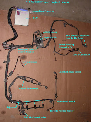
If you've come here then you have decided to undertake the task of wiring up an s13sr20det motor for use in a 1995-1998 240sx. This isn't the end all guide or going to go over problem free for you if it's your first time wiring up an engine. But it will get you set on the right path. - Wayne Tips before you get started on buying stuff. make sure you only use adhesive heat shrink. Just so happens a strand of h/s I bought wasn't adhesive and the solder ended up corroding causing shorts/issues. I had to cut open the whole harness and replace all of the heat shrink to be sure. Extra runs of wiring aren't really necessary to do this, you can use wires from your ka24de harness that are already color matched and the same gauge. The s13sr20det harness can have about 3-4 inches removed from it behind the firewall (in car) but don't make any cuts until you know everything works, then shorten as desired. If you break a plug/connector (use your brain a...